Overview
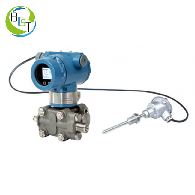
Model JCMT Intelligent Transmitter is a kind of multi-sensor field communication devices with microprocessors. In bi-directional communication mode,
it can follow HART protocol to apply FSK signal onto 4-20mA output signals. According to corresponding communication protocols, its management software,
JCMT , allows configuration, scanning and test for the transmitter with a PC.
Furthermore, it can also chat with its communication equipment with its manual controller. For “on-site” operation, one “On-site Push-button” control unit can be utilized. If the transmitter is equipped with an LCD display instrument head, an “on-site” push-button can be used to perform external configuration and parameter definition for the transmitter. Housings of standard products should be coated with paint, lest that corrosive atmosphere corrosion might happen. Process
connection can be fulfilled with stainless steel or Hastalloy C. Main relevant data of the transmitter can be Model JCMT Multi-parameter Transmitter
referenced on the nameplate, such as transmitter model, communication protocol, measure range, working voltage, output signal, instrument sequence number and etc. The instrument sequence number is valid throughout the world. If inquiry is necessary, please provide the instrument sequence number. As for explosion-proof type transmitters, their nameplates should be labeled with explosion-proof type.
The transmitter adopts modularized design. It consists of a differential pressure sensor module with integrated electronic adapter unit, an amplifier module with a control unit and a two-wire system RTD input terminal to measure process temperature. The sensor module adopts full-welded
structure, interior of which is a twin-barrel system with an intact overload isolation diaphragm, and one absolute pressure sensor and one differential pressure sensor are installed inside. The absolute pressure sensor is only installed on the high-pressure side, and the measured pressure will be taken
as reference value, in order to compensate influence from static pressure. The differential pressure sensor is made up of one capillary tube connected with negative pole of the sensor module. An additional differential pressure (Dp) will be applied onto diaphragm of the differential pressure sensor
through the isolation diaphragm and filler liquid. Check for tiny variation of the diaphragm, which shall result in changes of output voltage of the testing system. The voltage signal direct proportional to the input pressure will be digitalized through the adapter before being transmitted into the amplifier, and
then the amplifier will perform linearization on the signal as well as temperature compensation. Then, three values of Dp, P and T can be converted signals direct proportional to mass flowrate through compensation. Except for mass flowrate (Qm), Dp, P, T and Qv can also make for other
purpose of application. According to differences of transmitter models, connection between the transmitter and process can be fulfilled through female screw on elliptic flange on the transmitter, or connection between remote flanges and process pipelines or flanges.
The transmitter adopts a two-wire system, the same pair of leads in which can be used to connect working voltage, signal outputs (4~20mA) and digital quantities. Electrical connection can be fulfilled through interconnection with terminals through cable inlet.
Stainless steel hang tags for tag number are optional. Both upper and lower limits of the user’s range can be defined with “on-site” push-buttons. The transmitter can be equipped with an LCD display instrument head for direct readings (optional and replaceable). The “on-site” push-buttons and the LCD display instrument
head can be used to perform transmitter main function/ data configuration and external parameter definition.


